

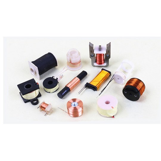
Copper Wire Coils for Your Assembly
- Copper conductor with the insulation specified for the winding.
- Coil dimensions that include the finished winding envelope.
- Self-supported, bobbin or magnetic core construction as required.
- Turns, winding direction and any separate connections identified.
- Lead exits and terminal preparation shown on the drawing.
- Electrical targets stated with the conditions used to measure them.
When a Custom Copper Winding Helps
- The winding must follow a housing shape or mounting space.
- A standard coil has unsuitable lead positions or connections.
- Wire size and winding layout need to meet a defined resistance target.
- The circuit needs a particular turn count, tap or winding section.
- The coil must be handled as a component in a larger assembly.
- Your drawing needs the mechanical and electrical requirements in one place.
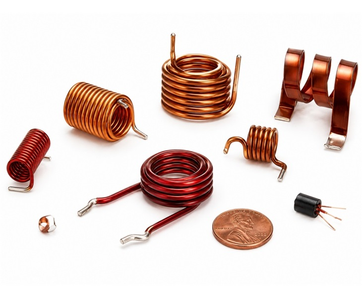
Custom Copper Wire Coils for Electrical Assemblies
JHCOILS manufactures custom copper wire coils and coil assemblies to customer drawings and specifications. Self-supported windings, bobbin wound coils and magnetic core windings offer different ways to fit the winding into an assembly. The conductor, insulation and connection details belong in the same part definition.
A copper winding can provide magnetic coupling, sensing, electromagnetic actuation or an inductive circuit function. Its dimensions and electrical properties depend on the complete construction. Start with the job the coil must perform, then compare the winding geometry, support and lead arrangement.
For quotation and sample review, specify the finished winding dimensions as well as the conductor. Insulation build, bonding, support and lead exits all occupy space. State electrical targets with their measurement conditions so proposed windings can be compared on a consistent basis.
Choose the Features of the Winding
Choose the winding profile, support and layer arrangement to suit your assembly. These features can be combined: a rectangular winding, for example, may also be self-supported and multilayer.
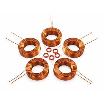
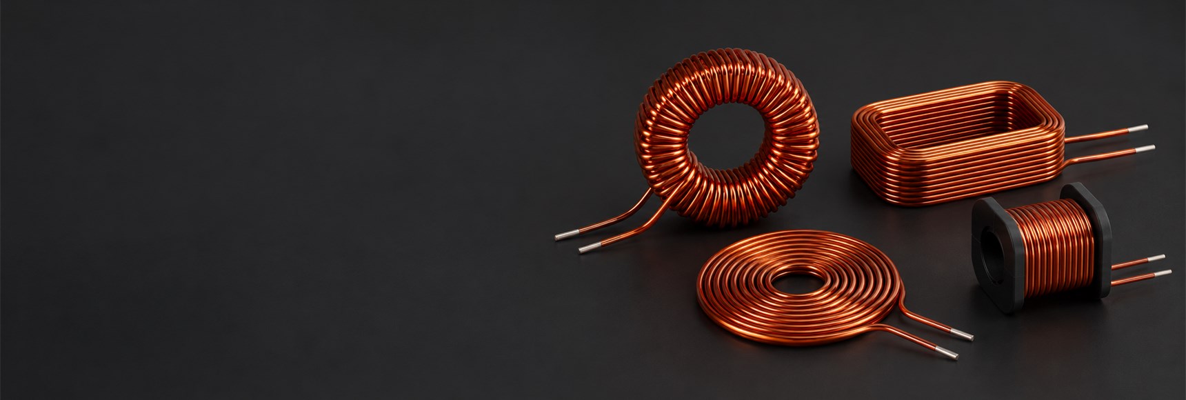
A circular winding arranged around an opening or cylindrical form. Inner clearance, wound diameter and axial length define the space it occupies.
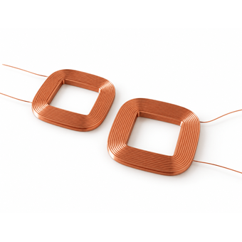
Straight sections and formed corners follow a rectangular envelope. Include the corner geometry and the space needed for the finished insulation.
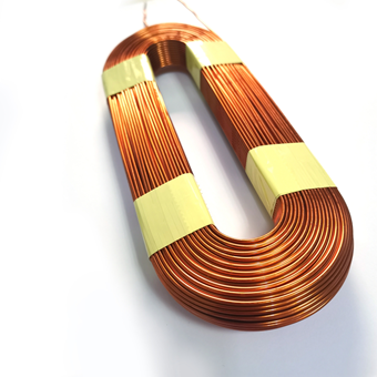
An oval or another agreed profile can follow a specific assembly. The drawing needs to define the profile rather than relying on a descriptive name.
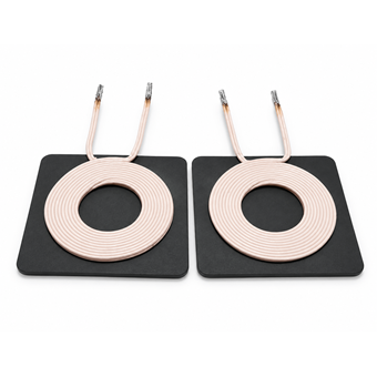
Turns lie mainly in one plane around a central opening. Consider the outer profile, stack height and how the two winding ends reach their connections.

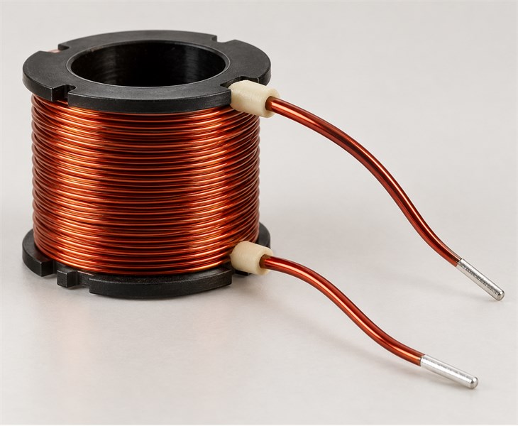
Bonded turns retain the winding form without a permanent bobbin. Support during handling and installation remains part of the assembly review.
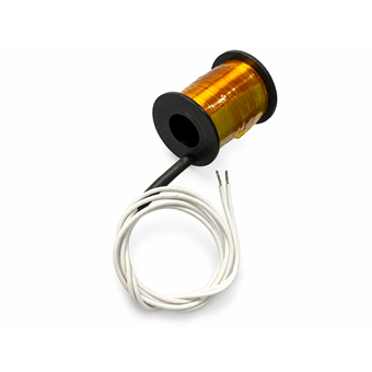
A former locates the winding and may carry mounting or terminal features. Its dimensions must be included when checking the finished part.
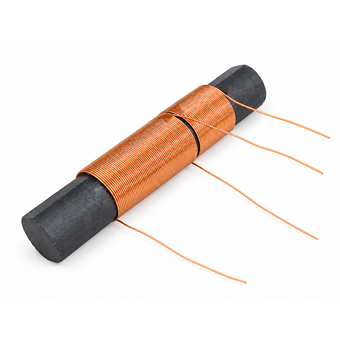
The copper winding works with a ferrite or other specified magnetic core. Core material and geometry affect the electrical behavior of the assembled component.
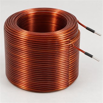
Turns occupy more than one layer. Layer arrangement, insulation and lead exits need to be considered together when defining the wound envelope.
Select the Job the Coil Performs
The external shape does not identify the circuit function. Begin with the required electrical task, then review the winding and supporting parts.
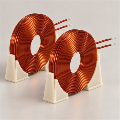
A winding transfers energy or a signal through a magnetic field. The partner coil, separation, alignment and connected circuit influence the result.
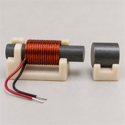
A sensing winding develops a signal in a changing magnetic field. Evaluate its response with a defined field source, loading and measurement arrangement.
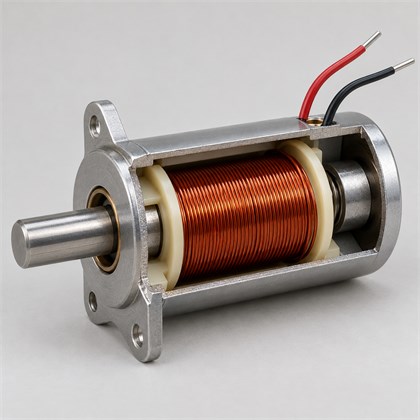
Current in the winding contributes to the force produced by a magnetic assembly. The magnetic circuit, duty and thermal conditions belong in the design review.
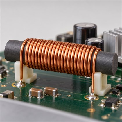
A winding may serve an inductor or choke function. Its impedance and behavior at the relevant frequency and current matter alongside nominal inductance.
Review the Conductor and Its Insulation Together
Conductor shape, strand construction and insulation are separate choices. The options below describe what to discuss for the complete winding.

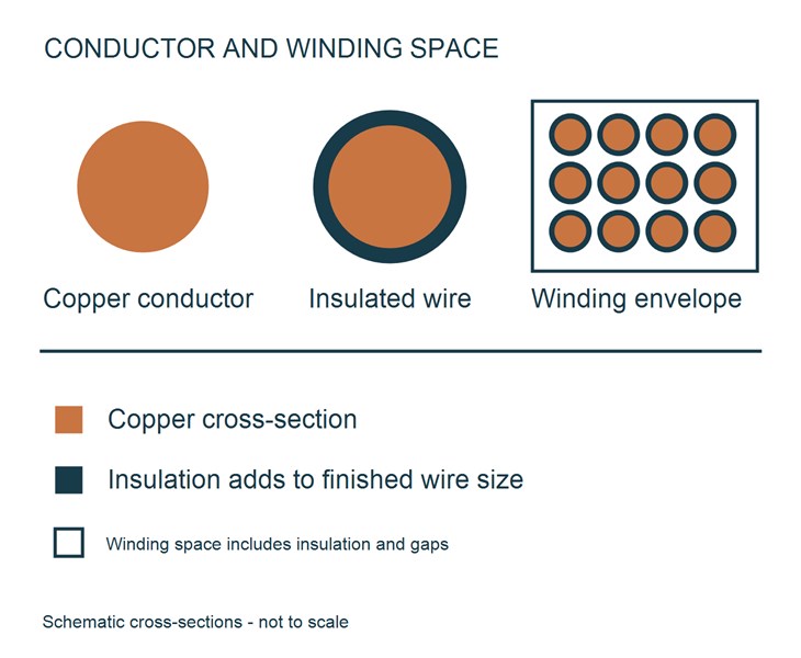
A solid copper conductor with an insulating film. Bare conductor diameter and finished wire diameter answer different electrical and winding space questions.

A rectangular section provides another way to arrange copper in the available space. Width, thickness, bends and insulation build need to be specified.

Individually insulated strands can reduce AC winding losses in suitable designs. Frequency, current, strand construction and termination determine whether it is useful.

A bonding layer can hold turns together, while the insulation separates conductors. Their functions and finished dimensions should be considered independently.
Check the Coil in the Intended Assembly
A winding can meet a bench measurement and still encounter a fit or connection problem. Check the conditions that change when the part is installed.

Include insulation, bonding material and lead exits when checking the available clearance.

Use the actual current waveform and duty when planning the thermal evaluation.

Identify winding starts, finishes and taps wherever polarity or connection order matters.

Keep handling and assembly forces from damaging the winding or loading its wire ends.

Check the effect of nearby metal and magnetic parts in the installed position.

Agree the relevant frequency, excitation and fixture before comparing electrical results.
Check Resistance in the Intended Operating Conditions
A thicker copper conductor can reduce DC resistance for a given wire length, but it also occupies more winding space. Changing the number of turns or the available winding envelope changes the comparison. Review the complete winding rather than selecting wire size in isolation.
For an AC copper winding, DC resistance alone does not describe the losses. Frequency, current waveform and nearby conductors affect AC behavior. Litz or flat wire may be appropriate for a particular design, but neither is a universal upgrade. Compare candidate windings under the electrical and thermal conditions that matter in the equipment.
Include the Connections in the Coil Drawing
A winding that fits the housing still needs usable connections. Show the lead exit direction, free lead length, stripped or tinned region and the required terminal or connector arrangement. Identify winding starts, finishes and taps when polarity or connection order matters.
These details affect how the copper coil reaches the next assembly step. Insulation must remain intact where the lead passes the winding or housing, while the contact area needs the agreed preparation. JHCOILS can discuss the winding and lead details together using your drawing. Any added support, connector or finishing operation should be included in the quoted scope.
Prepare the Information for a Copper Coil Review
Organize the winding envelope, electrical targets, connections and quantities before a quotation discussion.
Keep the sample identification, fit observations, measurement conditions and open changes in one record.
Compare round, flat and Litz conductors without confusing bare copper dimensions with the completed winding.
Custom Winding With the Connection Details Included
JHCOILS supplies custom wire coils and coil assemblies from customer drawings and specifications. Our product range includes wireless charging, RFID, motor, camera and antenna coils, with winding, lead preparation and inspection included in the manufacturing process.
For your copper coil project, we can discuss the winding geometry and the connections your assembler will use. Include any supporting parts or additional assembly work in the enquiry so the quotation can cover the required component and finishing scope.
Copper Windings in Different Equipment Functions
The equipment function determines which coil requirements matter most. Consider the circuit, magnetic arrangement and installation conditions alongside the winding dimensions for each application below.
Transmitter and receiver windings operate with a matching circuit and a defined coupling arrangement. Winding dimensions, alignment and the nearby magnetic or conductive materials affect how the system performs.
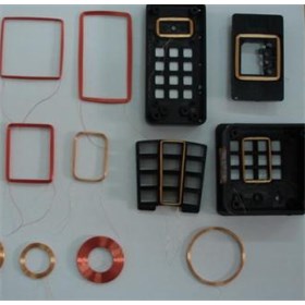
A reader or tag winding works within a particular frequency band. Evaluate its response with the intended electronics and mounting environment, including any surrounding metal that can change the coupling.
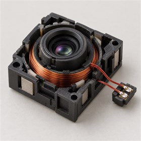
A small winding can form part of a movement or switching mechanism. The available envelope, moving or fixed connections and operating duty influence how the coil should be constructed.
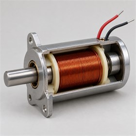
A motor or actuator winding operates within a larger magnetic structure. Winding position, connections, insulation and heat removal need to be considered with the complete assembly.
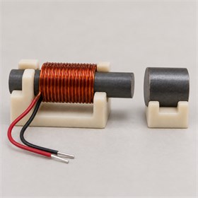
A magnetic pickup winding responds to a changing field. The signal requirement, interference environment and measurement arrangement matter when evaluating a proposed winding or comparing sample results.
Match the Review to Your Project Stage
An existing component and a new assembly provide different kinds of information. Make the starting point clear so the discussion addresses the right problem.
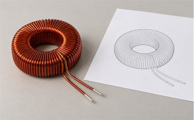
A reference part can show the physical construction, but its appearance may not reveal the insulation system, wire specification or intended operating conditions. Share the available drawing and measured data, and explain the reason for replacement. Identify the characteristics that must remain equivalent before comparing alternatives.
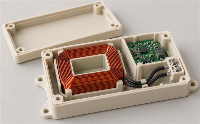
For a new housing or circuit, show the available winding space and the route to the connection points. Include the nearby parts that constrain fit or influence the magnetic field. Separating fixed limits from preferences helps focus the first winding proposal on the choices that affect assembly and operation.
Define the Coil Specification and Sample Review
Use the checklist to organize the requirements for your part, then record sample results against the agreed drawing and test conditions.
- Specification Checklist
- Sample Review
- Coil Gallery
| Item | Requirement to Agree |
|---|---|
| Application | Circuit function, frequency range and operating environment |
| Conductor | Material reference, bare dimensions, strand construction and insulation build |
| Winding geometry | Inner clearance, finished outer size, height and relevant corner geometry |
| Construction | Turn count, layers, support or core and winding connections |
| Electrical targets | Required values and tolerances with the measurement conditions |
| Connections | Lead exits, free length, end preparation and terminal identification |
| Thermal conditions | Current waveform, duty, ambient conditions and agreed acceptance basis |
| Supply scope | Sample and production quantities, added assembly and required documents |
When sharing sample feedback, identify the part and drawing revision, describe the installation and include the test conditions with the results. Separate a fit issue, a connection issue and an electrical measurement so each can be assessed against the relevant requirement.
For a proposed change, explain what it is intended to correct and which approved characteristics must remain the same. Discuss any revised sample or further evaluation needed before the change is treated as suitable for production.
Customer Feedback
A gauge change is a design change that needs review. It alters conductor resistance and the space taken by each turn; keeping the same external size may then require another winding arrangement. Lead preparation can also change. Compare the revised winding against the electrical targets and assembly constraints rather than approving it from wire diameter alone.
Matching nominal inductance is not enough to establish interchangeability. Resistance, frequency response, current behavior, insulation, dimensions and connections may differ. A magnetic core can introduce further differences. Evaluate the proposed copper winding against the relevant requirements of the actual circuit, using agreed measurement conditions and the installed configuration where it affects the result.
The instrument, fixture and measurement settings can influence the result. Inductance and Q depend on frequency, and the connections used for measurement introduce their own effects. Compare results using an agreed frequency, excitation level, relevant bias and fixture method. A difference between readings should be investigated before it is treated as a winding defect.
The wire insulation class alone does not establish a finished coil operating limit. Bonding materials, the bobbin, lead insulation and other assembly parts can impose different limits. Ambient temperature and heating during operation also matter. Specify the conditions for the complete coil assembly and confirm the supporting material information for the selected construction.
Explore the Relevant Coil Construction
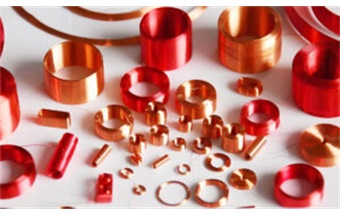
Review a winding construction that retains its shape without a permanent bobbin.
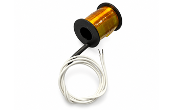
Review former based windings where the support and terminal arrangement affect the finished part.
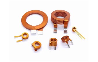
Explore rectangular conductor windings and the dimensions that define their copper section.
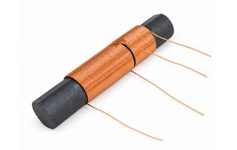
Review copper windings used with a ferrite core and a defined magnetic geometry.
Buying a Custom Copper Coil
A clear purchasing specification connects the required electrical function to a part that can be wound, connected and evaluated in your assembly.
A clear purchasing specification connects the required electrical function to a part that can be wound, connected and evaluated in your assembly.
Start with the drawing and requirements you already have. Identify fixed dimensions, electrical targets and any open choices. State the sample and production quantities separately so the enquiry reflects the stage of your project.
Separate Essential Limits From Preferences
Not every dimension or material choice has the same effect on the project.
Identify the limits imposed by the housing, circuit and connections. Where a feature can change, describe the acceptable alternatives or the result that must be preserved. This helps keep the review focused on the characteristics that affect interchangeability and use.
Define What the Sample Needs to Demonstrate
Component acceptance and equipment performance are related but distinct.
List the component checks needed for your project and evaluate the sample in the intended assembly where relevant. A winding measurement can confirm a defined property; it does not on its own establish charging performance, actuator force or sensing accuracy for the finished equipment.
State the Delivery Scope in the RFQ
A wound component and an assembly with prepared connections are different purchasing scopes.
State sample and production quantities separately. Include any supporting parts, added assembly, packaging or documentation your team expects. Use the same drawing revision for the quotation discussion and identify the requested destination and timing so proposals can be compared on a consistent basis.
You can start an enquiry with a drawing and the requirements already known. Identify the unresolved items so assumptions are visible before pricing is treated as firm. Include the application, available space and sample or production quantity. Where the wire, connections or acceptance requirements remain open, those choices need to be agreed as the quotation is developed.
Compare the same drawing revision, material definition, quantities and delivery scope. Separate any tooling or setup, sample work, unit price, additional assembly operations and required inspection documentation. Packaging and freight also affect the comparison. A lower unit price is difficult to assess if one supplier includes finished connections or extra checks and another prices only the winding.
Identify the earlier part and drawing revision, then describe the requested change separately from the requirements that stay fixed. Material, winding, connection and inspection changes can affect scope even when the coil looks similar. Ask for the quotation and any sample approval requirements to refer to the revised specification before the repeat order proceeds.