
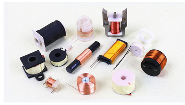
Coils Built Around Your Assembly
A coil has to fit the circuit and the assembly around it. Its outline, winding, insulation and lead positions all affect how it can be installed and used.
JHCOILS offers self-supported, bobbin-wound, ferrite-core and flat-wire constructions. We review your drawing and application requirements to discuss a suitable coil construction and prepare a quotation.
If your specification is still taking shape, share the dimensions and electrical targets you already know. These give us a starting point for discussing the details that still need to be agreed.
Explore Coil Construction Options
Start with the construction your assembly needs. These descriptions cover different design choices: support, core and conductor shape. A flat-wire winding, for example, may also use a bobbin.
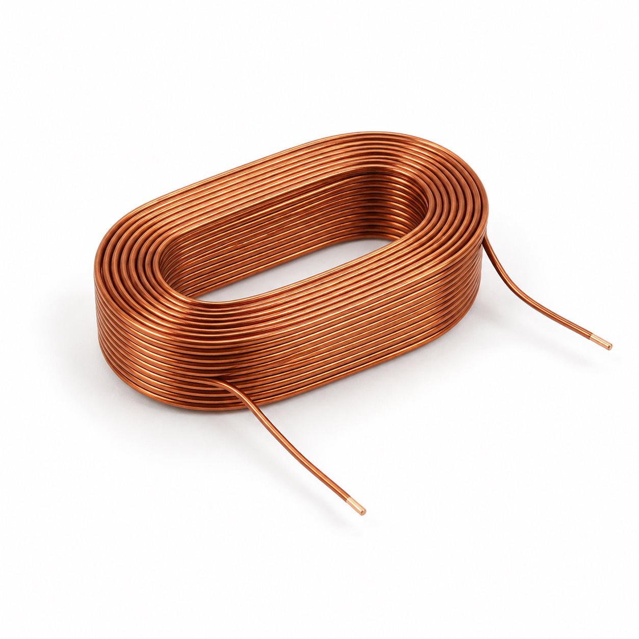
The winding holds its form without a permanent bobbin. This construction is useful when the coil must follow a defined outline and available space is limited. Handling and mounting still need consideration.
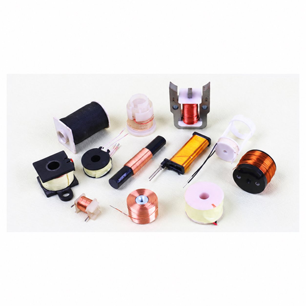
A bobbin supports the winding and provides a defined assembly interface. Its dimensions, material and pin or lead arrangement should match the surrounding components.
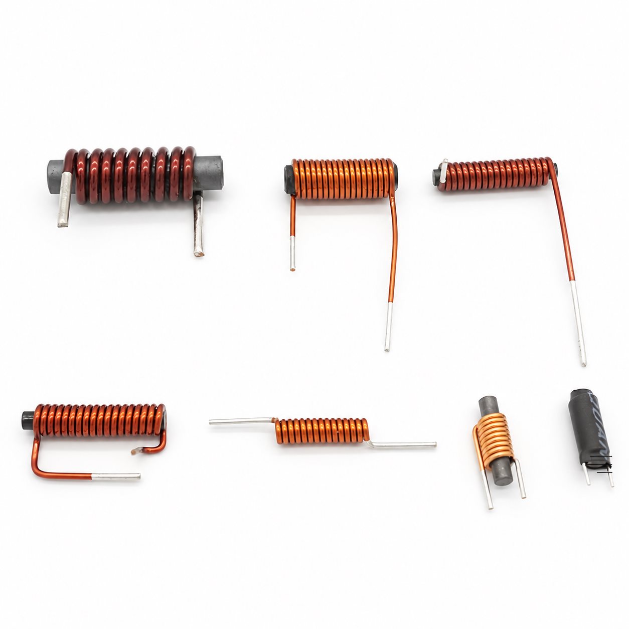
The ferrite core is part of the magnetic design. Choose the core and winding together around frequency, inductance and current requirements; the same outline does not guarantee the same electrical behavior.
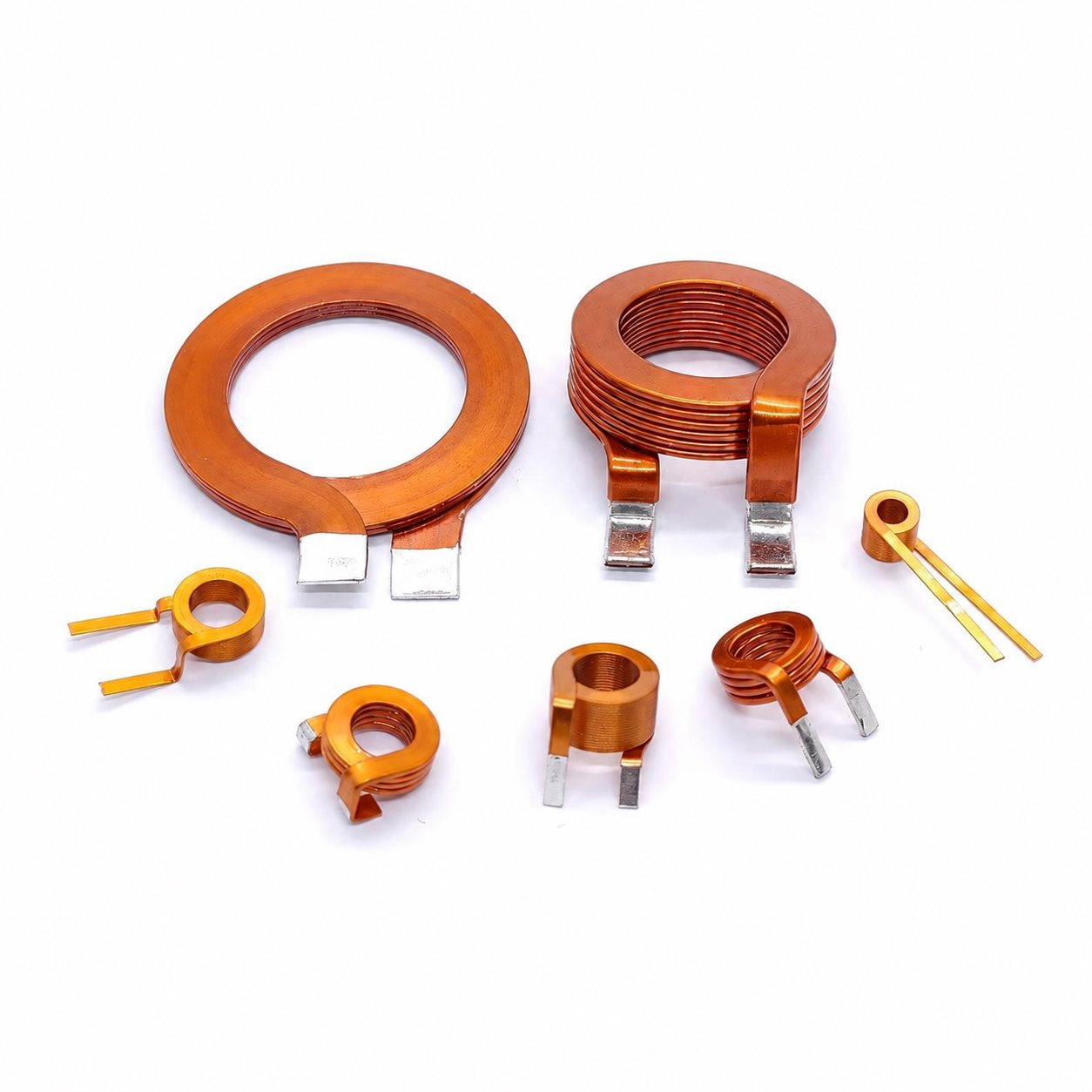
Rectangular wire changes how the conductor occupies the winding space. Assess its orientation, bend geometry and terminations against the available envelope and electrical requirements.
Define the Details That Affect Your Coil
A useful specification connects the electrical target with the physical part. The following details help separate fixed requirements from options that can be discussed.
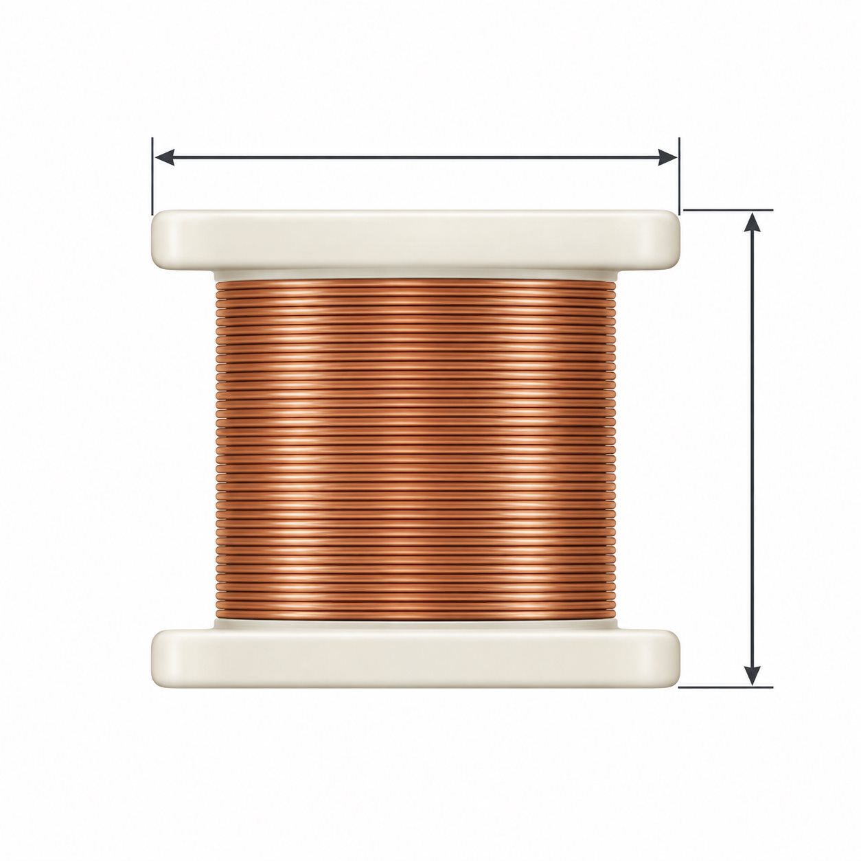
Identify the dimensions that control fit, including the inner opening, outer profile, height and mounting clearance. Mark critical tolerances on the drawing.
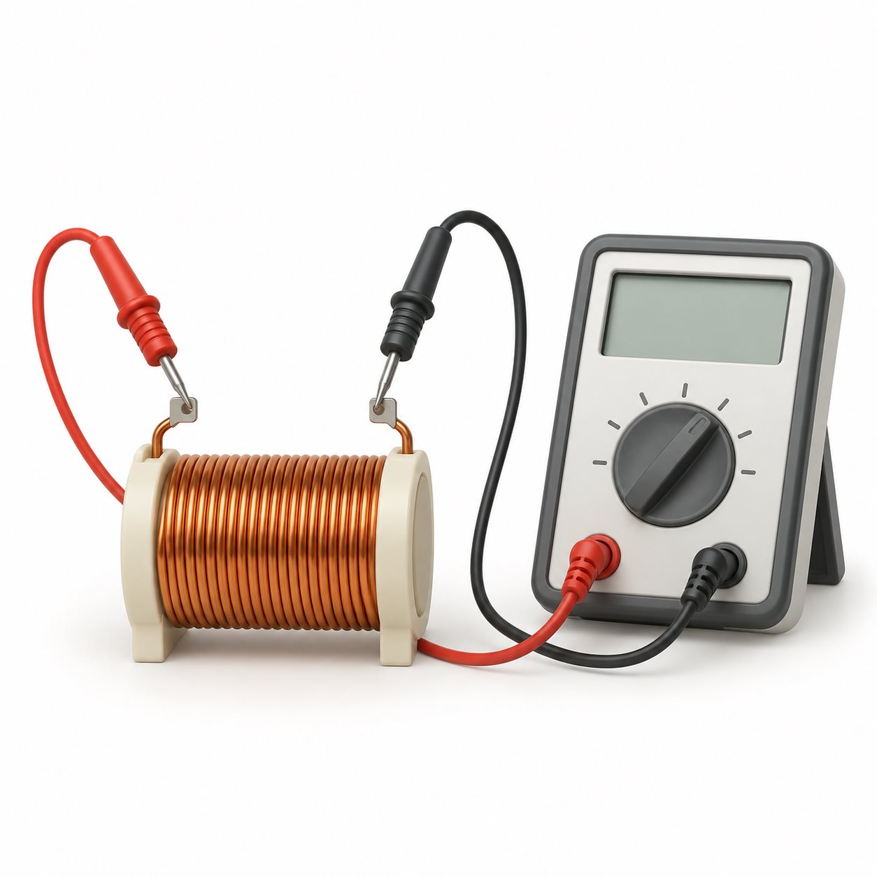
Specify the values that matter to the circuit, such as inductance, DC resistance and operating current. Include tolerances and measurement conditions where applicable.
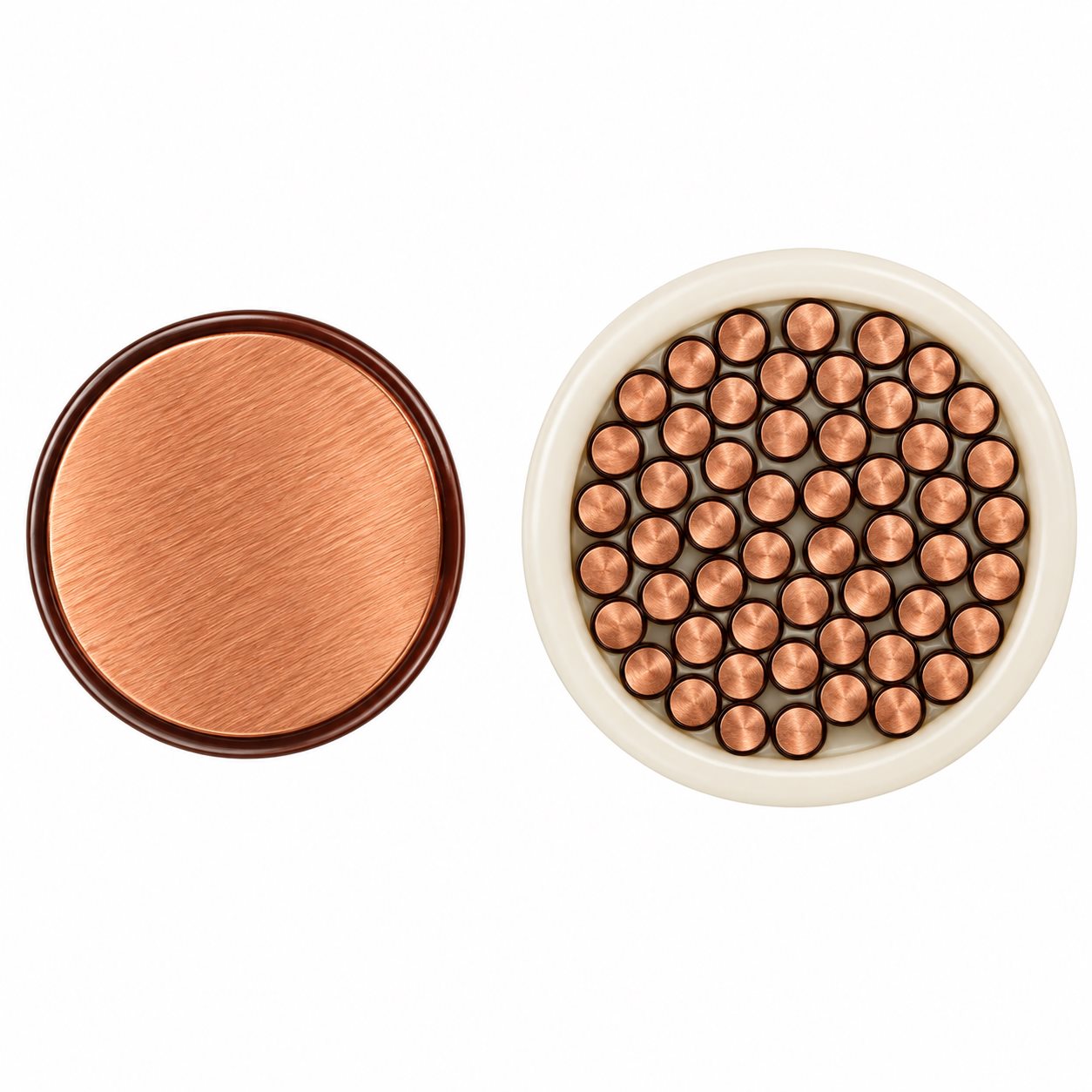
Specify the approved conductor size and insulation. If wire selection is still open, identify whether the design calls for single-conductor magnet wire or Litz wire.
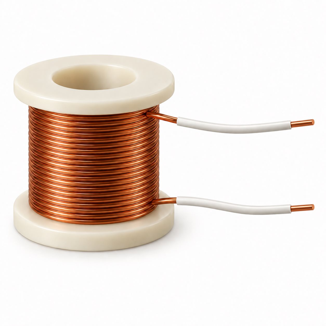
Show lead length, exit direction, stripped areas and the required connection. These details determine how the coil reaches the PCB, cable or terminal.
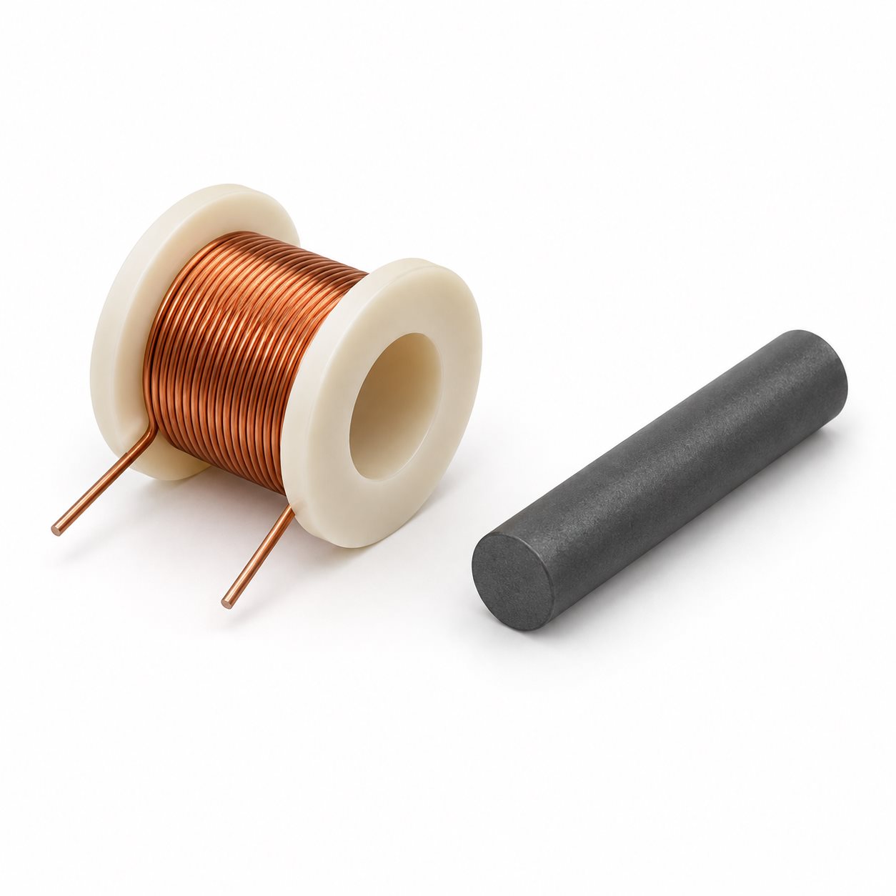
Identify any required core, bobbin or former, including material and part references. Note whether you will supply these components or need them included in the quotation.
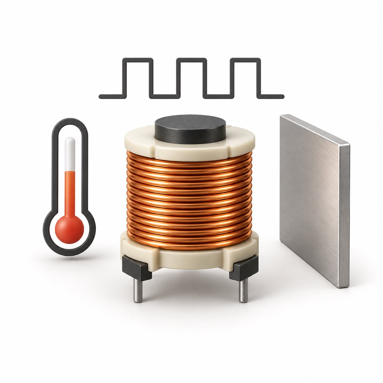
Describe the temperature range, duty cycle, nearby metal and other assembly conditions that may affect the winding. Include applicable insulation or compliance requirements.
Agree on How the Coil Will Be Accepted
Set acceptance criteria alongside the drawing. Inductance and Q can vary with test frequency and setup, so a nominal value alone may not be enough to compare measurements. Identify the relevant test conditions and the limits each result must meet.
Sample approval should also address physical fit, lead position and the intended assembly conditions. Record the approved drawing revision and any agreed changes before placing a repeat order. Ask for the inspection records your purchasing or quality team needs as part of the quotation.
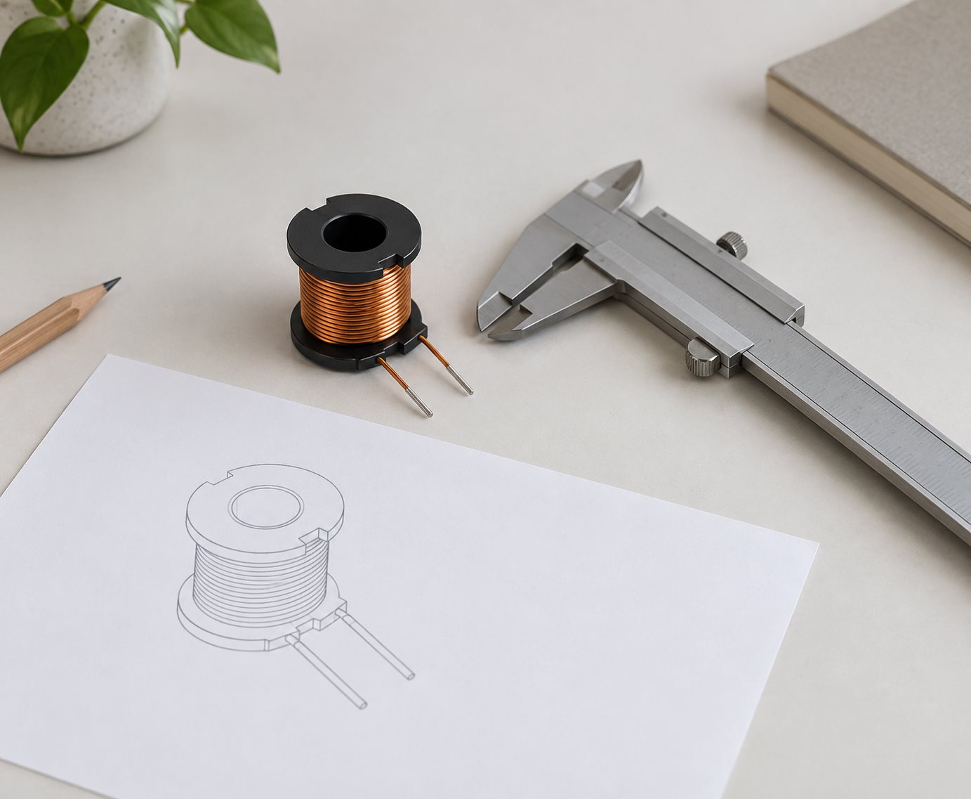
Match the Winding to Its Application
The application helps identify which requirements deserve attention first. Use these examples to describe the role of the coil in your product.
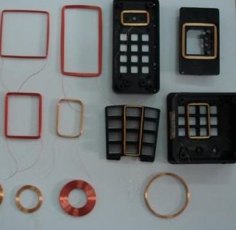
In an inductively coupled RFID design, the winding is part of the antenna circuit. Frequency, geometry and the tuning arrangement must be considered together. Check the coil in the intended assembly, including nearby conductive materials.
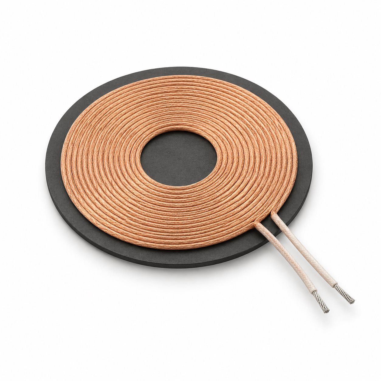
A transmitter or receiver winding must fit its charging assembly. Coil position, separation and any magnetic backing belong in the design brief. Coil data alone cannot establish the charging performance of the finished system.
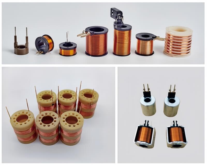
A solenoid winding works within a magnetic and mechanical assembly. Specify the available space, drive conditions and duty cycle. Force and movement depend on the complete device as well as the winding.
Questions About Custom Electronic Coils
Compare relevant coil constructions, drawing requirements and acceptance criteria before comparing price. Ask how the supplier will handle the wire, support, connections and inspection records specified for your part. A useful quotation identifies what is included, what requires clarification and which assumptions affect cost or delivery.
The terms overlap, but they are not interchangeable. An inductor is a component used for its inductance; a wound coil may form part of one. Coils also serve other roles, including antennas and electromagnetic actuators. Describe the function in your circuit or device so the inquiry reaches the right product discussion.
Yes. You can start an inquiry with a sample, reference images or application requirements. State which dimensions and electrical values are known. A sample alone may not reveal the original wire insulation, material grade or acceptance limits, so those details need to be resolved before a manufacturing specification is agreed.
Start with the space and support available in the assembly. A self-supported winding holds its shape without a permanent bobbin. A bobbin provides a defined winding support and may provide mounting or connection features. Compare fit, handling, insulation and lead routing for the actual design; neither construction is automatically the better choice.
Litz wire may help reduce AC winding losses when its strand size and construction suit the operating frequency. It uses multiple individually insulated strands arranged in a bundle. Compare frequency, current, winding space, insulation and termination requirements before selecting it. For an existing design, retain the approved wire specification unless a change has been evaluated.
Include the test frequency, excitation level, tolerance and any relevant DC bias or fixture conditions. Inductance readings can change with measurement conditions, particularly near resonance or under bias. Use an agreed method when comparing samples with production parts, and specify other acceptance measurements separately where they matter to the application.
Include the drawing revision or available sample information, electrical targets, critical dimensions, wire and core requirements, and connection details. Add the sample quantity, expected order quantity, delivery destination and required date. Identify required documentation and separate mandatory specifications from preferences so alternatives can be discussed clearly.
MOQ and lead time depend on the specific construction and order. Material availability, tooling, setup, sample approval and inspection requirements can all affect the quotation. State both your initial quantity and expected repeat demand, and ask for sample and production schedules separately. Confirm these terms for the agreed design before ordering.
Request a Quote for Your Coil
Send JHCOILS your drawing or describe the coil you need. The details below give us a starting point for discussing your requirements and preparing a quotation.
Existing part or sample. Include the drawing revision, critical dimensions and sample photos. Identify any dimensions, materials or connections that must remain unchanged.
Electrical and connection requirements. Share the inductance, DC resistance, operating current and measurement conditions where known. Add wire, insulation, lead length and termination details specified for your assembly.
Quantities and delivery needs. Tell us how many samples you need, the expected order quantity, delivery destination and preferred date. Distinguish a trial order from planned repeat requirements.
No complete drawing yet? Describe the application, available space and operating conditions. A sketch or reference photo can help explain the part. Note which requirements are fixed and where you need input.