JH-1203XY
Review the X/Y axis orientation, winding connections and package drawing.
Review XY references ↓
Compare JH-1203XY and 3D transponder coil references for low-frequency magnetic-coupling projects. Select by the required sensing axes, package dimensions, per-axis inductance and receiver interface.

Compare the winding axes with your receiver circuit, field direction and mounting arrangement.
Review the X/Y axis orientation, winding connections and package drawing.
Review XY references ↓Review all three axes separately, including their electrical values and terminal map.
Review 3D references ↓The references on this page are presented for 125 kHz design review. If your receiver uses another frequency, provide the IC reference and measurement requirements rather than assuming these parts are interchangeable.
The JH-1203XY reference uses a ferrite-based winding and mounting structure. Check the axis orientation, winding connections and package drawing against your receiver. Request sample availability and lead time in the quotation rather than relying on a stock statement.


The following values are historical web references. The available JH-1203XY document covers a different ordering code and does not establish resistance units for these rows. Request the selected part specification before ordering.
| Model | Listed L (mH) | Tolerance | Listed Q | Listed resistance* |
|---|---|---|---|---|
| JH-1203XY-1R9 | 1.97 | 3% | 35 | 90 |
| JH-1203XY-2R3 | 2.38 | 3% | 36 | 95 |
| JH-1203XY-3R3 | 3.3 | 3% | 36 | 98 |
| JH-1203XY-4R1 | 4.15 | 3% | 38 | 125 |
| JH-1203XY-4R9 | 4.90 | 3% | 38 | 165 |
| JH-1203XY-6R8 | 6.8 | 3% | 40 | 185 |
| JH-1203XY-7R2 | 7.2 | 3% | 48 | 232 |
| JH-1203XY-8R1 | 8.1 | 3% | 48 | 235 |
| JH-1203XY-9R0 | 9.0 | 3% | 49 | 278 |
| JH-1203XY-100 | 10.0 | 3% | 50 | 298 |
*Resistance units and measurement conditions require confirmation. No new resistance unit has been inferred.
Swipe the table to view all columns.
JH-1203XY model references are listed below. Confirm the current drawing, resistance units and electrical test conditions for the selected ordering code.
A 3D construction provides windings along X, Y and Z axes within one package. Review each axis separately: its inductance, Q, resistance, SRF and terminal map may differ. Confirm the footprint and assembly requirements before selecting a model.


| Reference model | X/Y L (mH) | X/Y Q (typ.) | Z L (mH) | Z Q (typ.) | X/Y SRF (MHz) | Z SRF (kHz) |
|---|---|---|---|---|---|---|
| 3D11LP-4720 | 4.7 ±4% | 26 | 7.2 ±4% | 15 | 1.9 | 850 |
| 3D11LP-6820 | 6.8 ±4% | 26 | 6.8 ±4% | 15 | 2.0 | 750 |
| 3D11LP-7220 | 7.2 ±4% | 26 | 7.2 ±4% | 15 | 2.1 | 700 |
Swipe the table to view all columns.

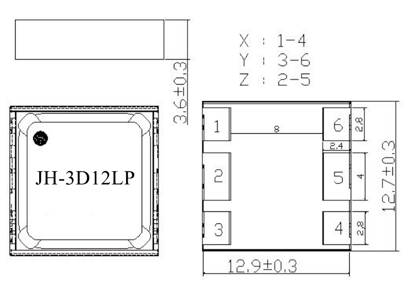
| Reference model | X/Y L (mH) | X/Y Q (typ.) | Z L (mH) | Z Q (typ.) | X/Y SRF (MHz) | Z SRF (kHz) |
|---|---|---|---|---|---|---|
| 3D12-6820* | 6.8 ±4% | 26 | 6.8 ±4% | 15 | 2.1 | 700 |
*The previous web listing used JH-3D12-6820. Confirm the actual supplied ordering code and drawing; the legacy reference uses 3D12-6820.
Swipe the table to view all columns.
Read Each Axis and Unit Separately
Tell us the receiver circuit, intended orientation, mounting process and operating environment. Automotive, medical or other regulated use needs its own qualification evidence for the exact part.